[GMC Main]
[6066 GMC Club]
[What’s New]
[Engines]
[Support]
[Memorabilia]
[GMC Gallery]
[GMC ID]
[VIN Numbers]
[Contact]
[
Discussion Group]
[Lighting & Electrical]
[V6 Performance]
Fuel Gauge Trouble Shooting
by Jolly Goodfellow with help from Gregory Smith.
Do you need to get your fuel gauge to start working? I guess this is a common problem in our trucks?
Before You start any testing, you will need a MultiMeter, I use a
Fluke Brand Meter. A Test light
is Ok but your better off with a meter, this way you can see the voltage you have, you can’t get
that info from a light. If using a light be careful not to fry any of you system. We Strongly Recommend
Reading Your Shop Manual Wiring Section Before You Do Any “Testing” On Your Electrical System!
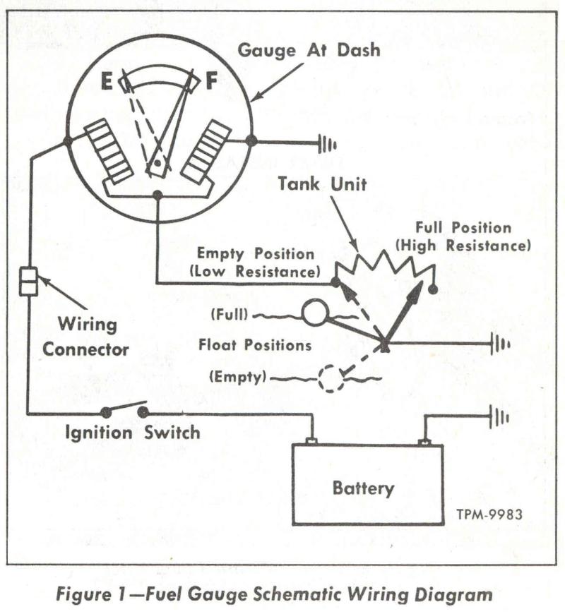
Fuel level in the tank is indicated by electrically operated fuel gauge system. Registering circuit is
located in the instrument cluster. the Position of the gauge pointer is dependent upon the amount of
current regulated through the dash unit coils by action of the float controlled unit in the tank.
The float is connected by an arm to a variable resistor in a manner that resistance is at a minimum
when the tank is EMPTY. As fuel level rises, the position of the float increases resistance in the tank
sending unit causing a change in current flow in the coils of the dash unit. This change in current
causes the pointer to deflect toward the full position.
The Fuel gauge is the balance-type, & Will allow the pointer to rest in any position between “Full” &
“Empty” when the ignition switch is in the “Off” position. This must not be interpreted as a defect
in the operation of the fuel gauge system. If tank or gauge unit becomes inoperative, the only
remedy is to replace the defective unit.
DO NOT PUT ANY BATTERY VOLTAGE INTO THE “Gas Gauge terminal”. The Tank sending unit
WILL be seriously damaged if full battery voltage is applied to the sending unit especially when the float
is at or near the “Empty” position. To prevent this occurrence it is recommender that a bulb of two (2)
candlepower or less, be used whenever a test is required. You may blow up or burn down your truck.
Testing the Fuel Gauge & Tank Float Sender System
Testing the Fuel Sending Unit:
Inspect all connections that are readily visible to insure that they are secure & free from dirt & Corrosion.
To Test for a bad sender, Disconnect the fuel tank sender wire at the tank. Ground the wire from the sending
unit at the fuel tank, the gauge should go to “Empty”. If it does, then test the ground at the sendering unit.
Connect a jumper wire between the fuel tank sending unit flange or pipe & a good ground. If gauge works,
connect permanent ground to the fuel tank sending unit. If not them the sender is bad. The gauge should read
“Full” when the wire is off. This test should be done with key in the “ON” position. This also will test your
Gauge & wiring. If you gauge reads Empty when you ground the fuel sender wire at the tank, the gauge & wiring
are GOOD. You can test the float with your MultiMeter on the ohm setting, you want some kind of Electric flow’
through the float assembly. In other words it should show some resistance. Replace sender unit if bad.
Testing the Fuel System Wiring:
If the sender is good, check the fuel gauge wires. The fuel gauge should have two wires, one will be
the power wire, check to see if you have power, it should read 12 volts (with key on). The other goes to
the sender, check to see if it shows a ground with the sender wire off at the tank. If it does, the
wire is grounded out some place between the gauge & tank. Now reinstall the wire at the tank, test
it for a ground. If it shows open or no ground in sender wire, with it on at the sender, then the wire
has a brake in it some place between the gauge & tank. Repair wire as needed.
Testing the Fuel Gauge:
If your gauge did not read “Empty” when you grounded out the Fuel Sender wire in the other test, & you
have checked the wiring in the system, it may be a bad ground at the gauge. use a jump wire, hook it
to the case of the gauge and known good ground, if your gauge works, repair the ground. If it does not
work, remove gauge from dash. With it removed put 12 volts to the power side, ground the gauge case &
ground the sender side. The Gauge should read “Empty”. Now remove the ground from the sender post, the
pointer should jump to “Full”. If not replace the gauge.
Check the plug on the back of the gauge panel, check the incoming side at the post lettered “D” & “E”.
“E” should be power to the dash, “D” is to the sender. Check the printed circuit board on the back of
the dash, (GMC Only). Look for brake in the printer on circuits. Repair anything found bad.
Maybe this simplified schematic will help.
If you put a test light on the “Gas Gauge terminal” in the fuse block, it will be dim. The reason why your
test lamp is dim at the “fuse block” (there isn’t actually a fuse there, it’s actually just a terminal
for the tank sender wire to plug in to, to continue on to the tank) is because there is a resistance
(the Gauge) between there & battery voltage. The voltage at that point should be around 3 volts. The
power comes into the gauge from a wire in the main harness that is feed off the key switch. When it
leaves the gauge it goes to ground through yet another resistor at the tank or the “sending unit”. The
terminal in the main fuse block is just an extension of the fuel gauge wire. It doesn’t provide power
to the sending unit from a fuse on the contrary, the sending unit is actually the ground for the gauge.
In other words, the connector gets its power from the gauge in the instrument cluster.
Water Temp Gauge Trouble Shooting
Electric type temperature gauge system consists of an engine thermal plug electrically
connected with registering gauge mounted on instrument panel. (Refer to applicable
wiring diagram). System is activated when ignition is turned on.
The engine unit is mounted in engine water outlet housing on straight-six & four cylinder engine, or in
engine water manifold on V6 gasoline engines. On diesel engine models, the water temperature indicator is
mounted on the outlet side of the engine front cover. Engine water temperature at these points, acting on
element in thermal plug, causes variation of resistance in electrical circuit.
Testing Electric Type Indicator
|
1. Disconnect wire at engine sending unit. Ground wire to
engine block. If gauge registers when ignition is turned on, you may have a bad sending unit, test as follows. |
|
2. Connect a test light consisting of a 12 volt, 2 candlepower
bulb, & a pair of test leads in circuit by clipping one lead to battery positive termainal & other lead to body of engine sending unit. If bulb lights, uint is properly grounded. If bulb dose not light, check for presence of sealing compound around threads ot unit. Remove compound & repeat test. Make sure unit is properly ground before proceeding with next test. |
|
3. Remove test lead from body of sending uint & connect lead to
termanal of unit. If bulb lights, engine sending unit is internally short-circuited & should be replaced. |
|
4. Remove test light & reinstall wire on Sending Unit.
|
|
5. If engine sending unit test satisfactory under the above
conditions, check the following items according to nature of difficulty. |
|
A. If gauge dose not register when ignition is turned on:
This may be caused by a break in the circuit between the gauge & the ignition switch or a short between this lead & ground. |
|
B. If gauge shows high temperature under all conditions; wire
leading from gauge & engine sending unit is shorted to ground. |
|
C. If gauge registers a low temperature under all conditions,
wire between gauge & sending unit is broken. |
Do Not Attempt to repair either the engine sending unit or the gauge. When installing new engine
sending unit, Do Not use thread compound on sending unit threads, as this will increase
electrical resistance og unit & cause faulty reading on gauge.
~ 6066 GMC Trucks ~ 6066 GMC Trucks ~
6066 GMC Trucks ~ 6066 GMC Trucks ~
6066 GMC Trucks ~ 6066 GMC Trucks ~
6066 GMC Trucks ~ 6066 GMC Trucks ~
 |
Lighting & Electrical Projects |
|
|
|
|
~
6066 GMC Trucks ~ 6066 GMC Trucks ~
6066 GMC Trucks ~ 6066 GMC Trucks ~
6066 GMC Trucks ~ 6066 GMC Trucks ~
6066 GMC Trucks ~ 6066 GMC Trucks ~
© 2000-2008 6066 GMC Trucks. Last Updated July 29, 2008.